
With the launch of SAP Process Integration 7.31 SP2 and Process Orchestration 7.31 SP2, the Eclipse tool was introduced to build End to End (E2E) integration scenarios. At the time of publishing this post, the Eclipse tool is used with existing Swing tools. Although the new Eclipse iFlow tool makes the old Swing Integration Directory client obsolete, in order to build E2E integration scenarios with mapping, iFlows should be used in conjunction with Enterprise Service Repository (ESR) Swing client.
Eclipse iFlow tool has some functionality of ESR swing clients such as the creation of SWCVs, Message Types, Mapping, Service Interfaces, etc., but it lacks the mapping testing tool which is crucial for Development Unit Testing. In the future, we will be able to build complete End to End scenarios using only the Eclipse tool while Swing clients could become obsolete.
Before we start creating our first E2E scenario using iFlow, we need to install NWDS for PI/PO development.
SAP Versions used in the illustration:
- SAP PO 7.5
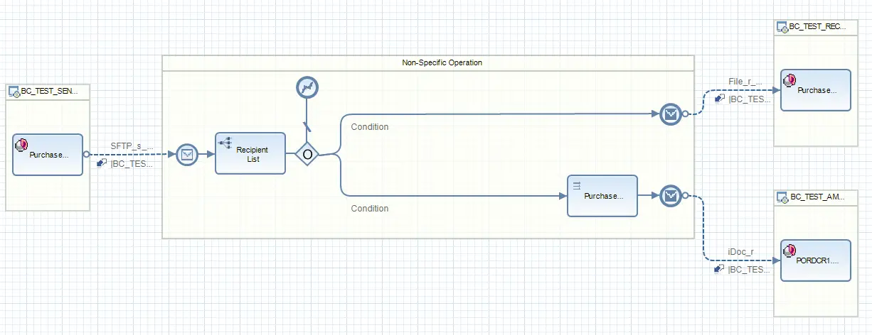
Sample End to End Scenario Overview:
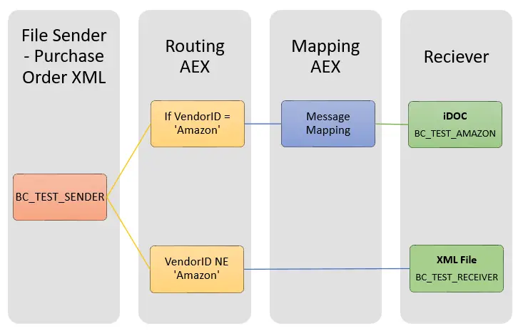
Let’s create an integration scenario to process Purchase Order XML sent from component ‘BC_TEST_SENDER’. If the ‘Destination_name’ in the XML file content is “AMAZON’, the message should be sent to BC_TEST_AMAZON in iDoc format. Else XML message should be forwarded to ‘BC_TEST_RECEIVER’.
Therefore, we require one Message Mapping between the sender XML format and Receiver iDoc format. But the creation of ESR objects will not be shown in the post as it is intended to illustrate how to create iFlows.
Step 1: Create Business Components in Eclipse NWDS PI Explorer.
For this scenario, we need to create three different Business Components. BC_TEST_SENDER, BC_TEST_AMAZON, and BC_TEST_RECEIVER. You can also use existing Business Systems or Business Components for your own scenarios.
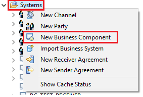
Right-click on ‘Systems’ and select ‘New Business Component’ to create a new one.
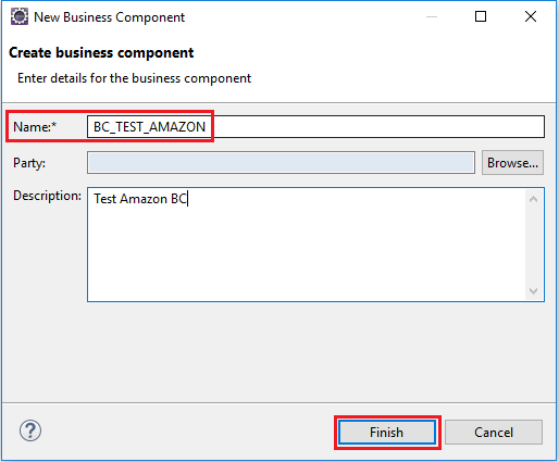
Similarly, create other two Business Components BC_TEST_SENDER and BC_TEST_RECEIVER.
Step 2: Create Service Interfaces, Message Mapping and Operation Mapping.
Create ESR objects either using Swing client or Eclipse NWDS. We will have one Outbound Service Interface ‘PurchaseOrder_Out_Async’, and one iDoc receiver Inbound Service Interface ‘PORDCR1.FSHPORDCR’ for Amazon. Also, one dummy Inbound Service Interface for BC_TEST_RECEIVER since it’s a pass through without mapping.
Operation mapping between XML File sender Service Interface and iDoc Receiver Inbound Interface should be created. Message Mapping for XML sender format and iDoc message type should be created as well.
Step 3: Create XML File Sender, File Receiver and iDoc Receiver Communication Channels.
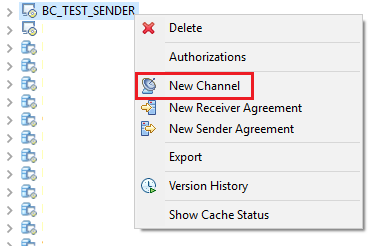
Create the Sender Communication channel by right clicking on the sender Business Component ‘BC_TEST_SENDER’. Configure the Communication Channel parameters.
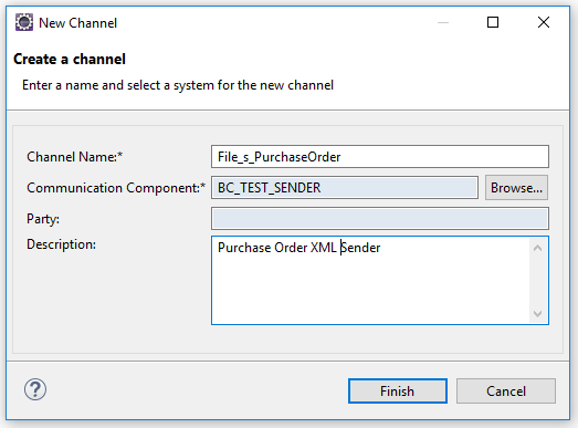
Save and activate.
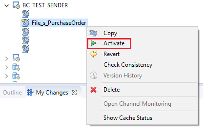
Similarly, create iDoc receiver channel for Business Component ‘BC_TEST_AMAZON’ and XML File Receiver Channel under ‘BC_TEST_RECEIVER’.
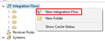
Step 4: Create New Integration Flow (iFLow) and Select iFlow Pattern.
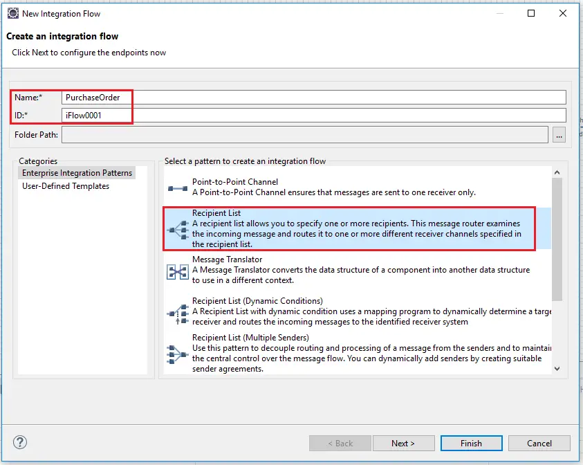
Select the appropriate Integration pattern and set the name and ID of the iFlow. Since example scenario involves one sender and multiple receivers, I have selected ‘Recipient List’ interface pattern.
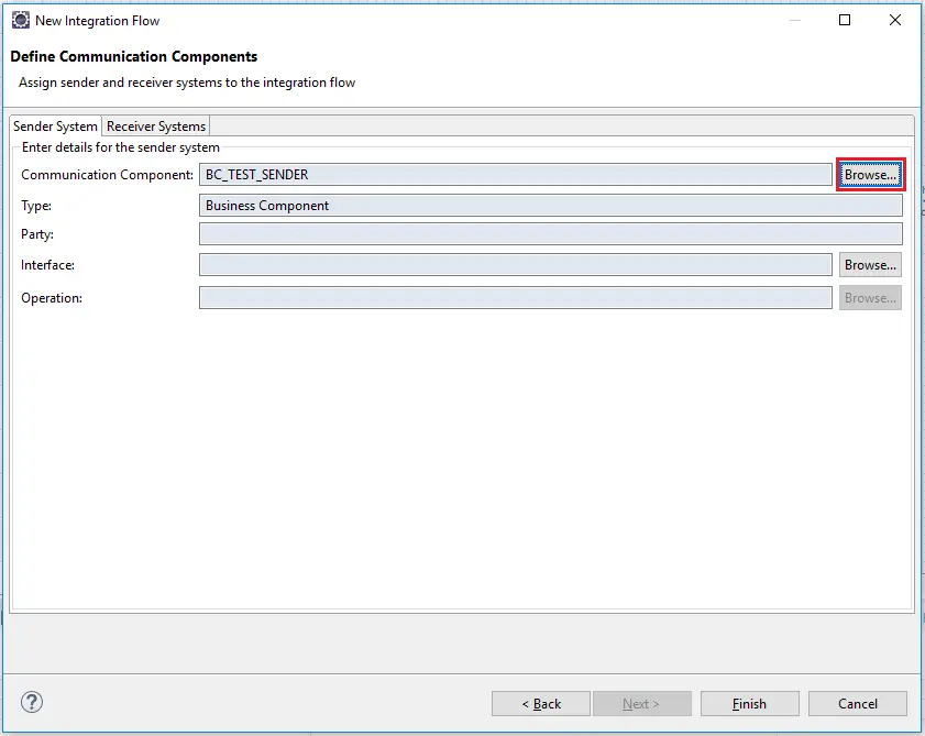
Step 5: Select Sender System and Receiver Systems of the Integration Flow.
Next step is to select all systems related to the integration scenario. Click ‘Browse’ and select the sender system and receiver systems from the drop down.
Go to tab ‘Receiver Systems’ and add both receiver systems.
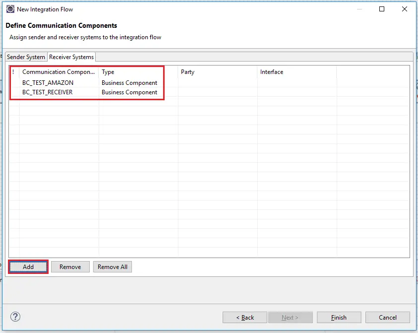
Click Finish.
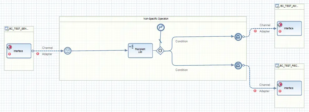
When you assign Business Systems and click “finish”, skeleton of the iFlow will be created. Your Next steps will be to fill the missing pieces of the iFlow such as Service Interfaces, Mapping, Communication Channels, Receiver Rules etc.
Step 6: Assign Service Interfaces.
In this step, we’ll fill in all Service Interfaces related to each system. Sender Outbound interface, Receiver iDoc Interface and Dummy interface for the pass through without mapping.
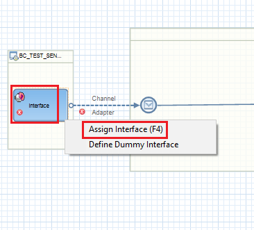
Right click on Interface component and select ‘Assign Interface’. Select the correct interface from the drop down list. For sender ‘BC_TEST_SENDER’ I am assigning ‘PurchaseOrder_Out_Async’ Outbound interface.
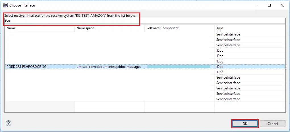
Similarly, assign the iDoc Receiver Inbound Interface from drop down list.
Step 7: Assign Communication Channels.
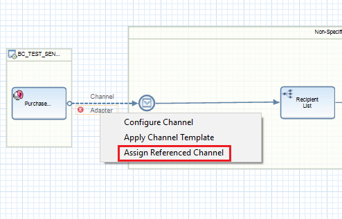
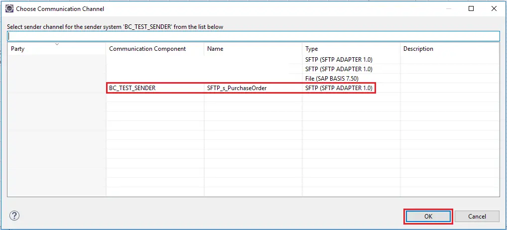
Assign the Communication Channels created in Step 3 to the iFlow. Right click on ‘Channel Adapter’ arrow and select the option ‘Assign Referenced Channel’. Communication Channel can be selected from the list of Communication Channels in the next window.
We used ‘Assign Referenced Channel’ since we had created all Communication Channels previously in Step 3. But new Communication Channels can be created here using option ‘Configure Channel’.
Repeat the step to assign the rest of the Communication Channels to the iFlow. iDoc Receiver channel to BC_TEST_AMAZON and File Receiver Chanel to BC_TEST_RECEIVER.
Step 8: Define the Receiver Rule.
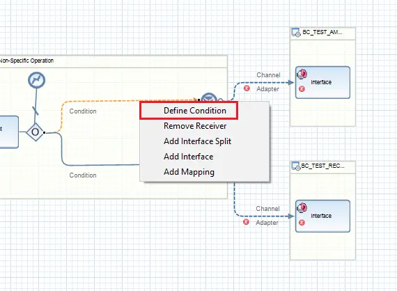
In this step, we will create the Receiver Condition based on Xpath of the XML to route message which should be send to Amazon. To insert a condition, right click on the ‘Condition’ arrow and select ‘Define Condition’.
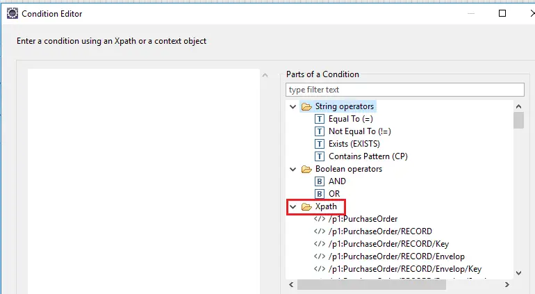
Select the Xpath and define the condition as below. Condition is defined for field <Destination_name> and value ‘AMAZON’.
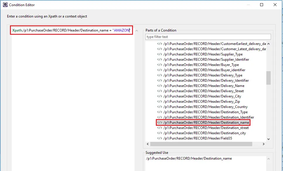
We can also use context objects instread of Xpath to define the same reciever rule.
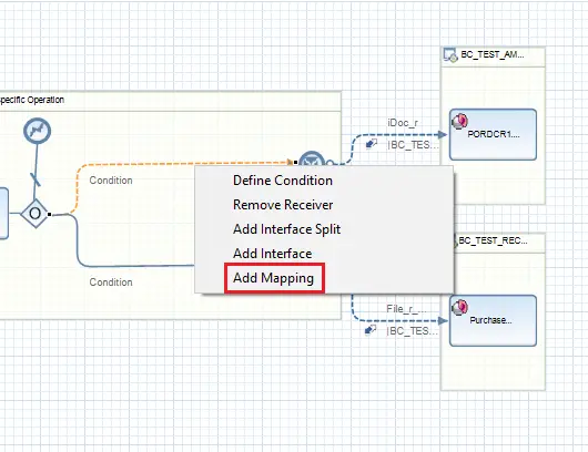
Step 9: Add Mapping to iFlow.
Right click on the ‘Condition’ arrow and select ‘Add Mapping’ option from the list to add a mapping step to iFlow.
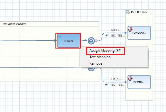
When you add a new Mapping to the iFlow, it will create a block named ‘Mapping’. Right click on the ‘Mapping’ and select ‘Assign Mapping’ option to choose the Operation Mapping created for XML sender to iDoc Receiver in ESR.
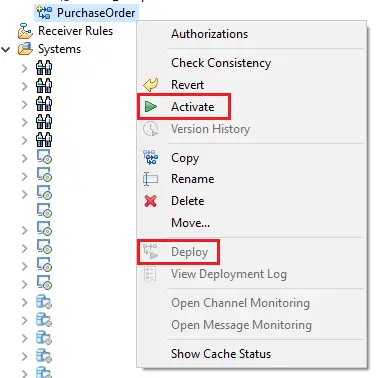
Step 10: Save, Activate and Deploy the iFlow.
If you completed all the steps and assigned the Service Interfaces, Mapping, Receiver Rule, Communication Channels successfully, you should be able to activate the iFlow after saving. If the Activation is successful, Deploy the iFlow.
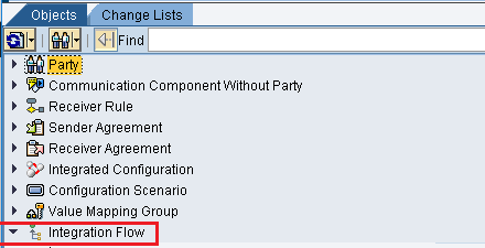
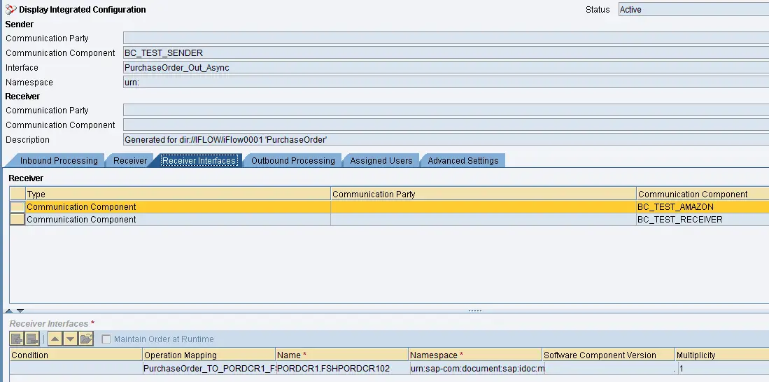
Step 11: Check if iFlow is Successfully Deployed.
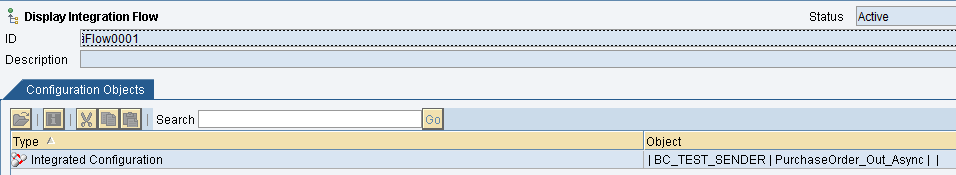
Go to Integration Directory and check if the iFlow is successfully deployed.
Once the iFlow is Activated and Deployed, corresponding Integration Directory objects, such as ‘Integration Flow’ and ‘Integrated Configuration Object (ICO)’, will be created.
Hope this article helps you to create your first iFlow and clarify any questions you have about iFlow creation steps. If you have more questions on how to use Eclipse based NWDS to create Integration Flows (iFlows), please leave a comment below.
Great blog isurubl fernando…
Please post any blogs on b2b scenarios
Do u have any idea idoc acknowledgement scenarios what are the configurations required..
Hello Sai,
Subscribe to the email list to get the latest updates on new posts! I will include more content about B2B.
Cheers!
Great Blog…
Please start posting topics on SAP cloud platform integration if possible…
Hi Sandeep,
Subscribe to email list so I can notify you when I post new content. I will try to include SAP Cloud related content.
Cheers!
Excellent explanation can u provide end to end scenario for jdbc to proxy for synchronous communication using request response bean module
Regards,
Siva ram
Hello Siva,
Thank you!! I will add it to my future article list 😉
Cheers!
Isuru
Great job, you made life easier.. Thanks a lot
Thank you Shoukat! Glad to hear the tutorial helped you.
Fantastic one!! Thanks a lot.
Please post another article with message mapping, how to import the structure, map the fields, using udfs etc.
Regards,
Sri
Hi Sri,
Definitely, I will try to write a post on basic PI/PO development steps in the future.
Cheers!
Isuru
please post the information on how to configure TPM( Trading Partner Management) settings for B2B scenarios.